7 Tips for Choosing a Plate Coil Heat Exchanger

Time:2026-10-14 Author:Amelia
0%

Selecting the right Plate Coil Heat Exchanger affects energy use, temperature control, maintenance, and plant reliability. The decision becomes more important as cooling demand rises worldwide. The International Energy Agency reports that global space-cooling demand could more than triple by 2050 under current policies. That trend places greater pressure on compact, efficient heat-transfer equipment.

Real projects rarely operate under perfect conditions. Water quality changes. Flow rates fluctuate. Fouling appears earlier than expected. A unit that performs well in a laboratory may struggle inside a humid process room. The ASHRAE Handbook emphasizes fluid properties, approach temperature, pressure drop, fouling resistance, and control stability when engineers size heat exchangers. These details matter more than attractive catalog numbers. They also reveal a common mistake: choosing equipment by capacity alone.

This guide presents seven practical tips for evaluating a Plate Coil Heat Exchanger. It considers thermal duty, coil material, circuit design, allowable pressure loss, cleaning access, corrosion exposure, and supplier support. AHRI Standard 400 provides recognized methods for rating liquid-to-liquid heat exchangers, but every application still requires careful verification. Published performance data is useful. It is not always complete.

Look closely at the operating details. A stainless-steel coil may suit clean water, while aggressive chemicals demand stronger material selection and testing. A narrow temperature approach can improve recovery, yet it may increase surface area and cost. Trade-offs are unavoidable. The best choice balances measured performance, service conditions, lifecycle cost, and credible technical evidence. Sometimes, the first specification needs revision. That is good engineering, not failure.
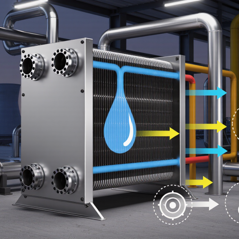
7 Tips for Choosing a Plate Coil Heat Exchanger

Define Heat Duty with Q = ṁCpΔT and a 1–3°C Approach Temperature

For a plate coil heat exchanger, sizing begins with heat duty, not surface area. Use Q = ṁCpΔT. Here, ṁ is mass flow, Cp is specific heat, and ΔT is the fluid temperature change. Keep units consistent. A 10 kg/s water stream, with Cp near 4.18 kJ/kg·K and a 5°C rise, needs about 209 kW. This simple calculation exposes weak assumptions early. The U.S. Department of Energy’s Industrial Decarbonization Roadmap identifies process heating as 51% of industrial energy use. Small sizing errors can therefore become expensive operating losses.

Tip: Treat the 1–3°C approach temperature as a design target, not a guarantee. A 1°C approach may require more coil area, tighter flow control, and cleaner surfaces. Fouling, viscosity, and seasonal load changes can quickly erase that margin. ASHRAE’s Handbook—HVAC Systems and Equipment emphasizes these variables during heat exchanger selection. I would not choose the smallest approach simply because it looks efficient. That choice can be too optimistic.

Tip: Calculate both design and part-load duty. Tip: Record inlet and outlet temperatures at commissioning. Tip: Check whether Cp changes across the temperature range. Tip: Allow practical fouling resistance. Tip: Confirm pressure-drop limits before approving the coil. Tip: Review control-valve authority. Tip: Recheck the calculation with measured flow.

The IEA’s Energy Efficiency 2023 report recorded global energy-intensity improvement of 2.2% in 2022, while noting faster progress is needed. Better heat-transfer design supports that effort, but field data still matters. The first estimate is rarely perfect.

Select 0.3–1.5 m/s Channel Velocity to Balance Fouling and Erosion

Choosing a plate coil heat exchanger starts with controlling channel velocity. A practical design range is 0.3–1.5 m/s. Lower speeds reduce pumping demand but may allow dirt, sludge, or biological growth to settle. Higher speeds improve surface cleaning, yet can increase erosion, vibration, and pressure loss. The correct point depends on fluid viscosity, suspended solids, temperature, and plate material.

Tip: Begin near the middle of the range, around 0.8 m/s, then adjust using operating data. For clean water, a higher velocity may improve heat transfer. For abrasive slurry, it may shorten service life. Check inlet and outlet pressure readings during commissioning. A small velocity change can reveal a developing blockage. Do not trust calculations alone.

Tip: Inspect the coil after several operating cycles. Look for deposits near the inlet, worn edges, unusual discoloration, or uneven flow marks. If fouling appears quickly, increase velocity carefully or improve filtration. If erosion appears, reduce velocity and review particle concentration. This balance is not always neat. Real systems drift.

Tip: Keep a margin below the maximum recommended velocity, especially during startup and control-valve changes. Transient surges can exceed the normal design value. Record flow, pressure drop, heat duty, and cleaning frequency. These records support safer adjustments and more reliable sizing. A perfect first selection is unlikely. Recheck it.

Match Plate Materials to pH, Chlorides, and Fluid Compatibility Limits

Choosing a plate coil heat exchanger starts with the fluid, not the equipment size. Plate materials must tolerate pH, chlorides, temperature, and chemical concentration together. pH is only one clue. A mildly acidic fluid may still attack metal when chlorides and heat rise.

Stainless steel can suit many clean-water and moderate industrial services, but chloride-rich water demands caution. Localized pitting may begin inside narrow plate gaps, where inspection is difficult. Higher-alloy stainless steel can improve resistance, while titanium often performs better in hot, saline applications. However, material strength, fabrication quality, and cost still matter. Do not guess.

Review the entire fluid chemistry. Check oxidizers, dissolved oxygen, suspended solids, and cleaning chemicals. A plate material compatible with the process fluid may fail when exposed to an aggressive cleaning cycle. Gaskets, brazed joints, and connection materials also need separate compatibility checks. They are part of the heat exchanger’s wetted system.

Use supplier compatibility data as a starting point, not a guarantee. Test a small sample when the fluid is unusual, concentrated, or constantly changing. A common mistake is selecting materials from pH alone. In practice, temperature and chloride concentration can change the corrosion risk sharply. Record normal and worst-case conditions before approving the plate coil design. The most reliable choice is the one supported by chemistry data, operating history, and a realistic maintenance plan.

Verify 10–25 bar Design Pressure and Applicable ASME or EN Standards

7 Tips for Choosing a Plate Coil Heat Exchanger

Confirm the design pressure before comparing heat-transfer area. For many plate coil applications, 10–25 bar is a practical screening range, not a final specification. Check whether the value is gauge or absolute pressure. Record the design temperature, vacuum condition, pressure cycles, and fluid density. The IEA’s Energy Efficiency 2023 report states that industry uses nearly 40% of global final energy, making reliable thermal equipment important.

Request material certificates and documented pressure calculations. Then verify whether ASME BPVC Section VIII applies to the complete assembly or only a pressure-retaining part. EN 13445 may be relevant for unfired pressure vessels in European projects. Do not assume a CE mark proves pressure suitability. The Pressure Equipment Directive uses risk categories and conformity routes based on pressure, volume, and fluid group.

Ask for hydrostatic test pressure, test medium, holding time, and acceptance criteria. A test pressure is not the same as continuous design pressure. Inspect weld maps, radiography records, and corrosion allowances. Pay attention to gasket compression and plate distortion. Small details matter.

Field reviews often uncover mismatched nozzles or undocumented modifications. That is avoidable, but not always avoided. Ask an independent engineer to review the datasheet against ASME or EN requirements. The choice may look obvious. It rarely is.

7 Tips for Choosing a Plate Coil Heat Exchanger - Verify 10–25 bar Design Pressure and Applicable ASME or EN Standards

Tip What to Verify Practical Design Data Applicable Standard or Reference Recommended Documentation
1. Confirm the pressure class Check the design pressure for each independent fluid circuit rather than relying only on the normal operating pressure. 10–25 bar(g)
10 bar = 1.0 MPa ≈ 145 psi
25 bar = 2.5 MPa ≈ 363 psi
Select a rating equal to or higher than the specified design pressure, including credible pressure surges.
ASME BPVC Section VIII, Division 1, or EN 13445 may be used for pressure-vessel design where applicable. Local pressure-equipment legislation may also apply. Stamped nameplate data, design-pressure calculation, pressure-rating certificate, and supplier data sheet for both circuits.
2. Separate design pressure from operating pressure Verify the maximum allowable working pressure, normal operating pressure, startup and shutdown conditions, blocked outlets, pump shutoff pressure, and thermal expansion scenarios. Example: if normal operation is 8 bar(g), a 10 bar(g) design rating may be inadequate when a pump can generate 12 bar(g). Relief protection and transient analysis should be considered. ASME Section VIII requirements for pressure-containing equipment; EN 13445 design rules; EN 764-7 provides guidance for safety systems on pressure equipment. Process design basis, maximum-pressure study, relief-valve set-pressure calculation, and operating envelope.
3. Check the applicable code route Identify the legal jurisdiction, fluid group, pressure-volume category, and whether the plate coil assembly is treated as pressure equipment or an integrated component. For equipment placed on the European market, determine whether the Pressure Equipment Directive applies and document the conformity-assessment route. For other jurisdictions, confirm the authority having jurisdiction and adopted code. ASME BPVC Section VIII, Division 1; EN 13445; PED 2014/68/EU; and harmonized or referenced material, welding, inspection, and testing standards as required by the selected route. Code-design statement, PED classification assessment where relevant, conformity documents, and inspection plan.
4. Match materials to both fluids Evaluate corrosion, erosion, pitting, stress-corrosion cracking, galvanic effects, and compatibility with cleaning chemicals on the hot and cold sides. Common engineering choices may include austenitic stainless steel for many water-based services, nickel alloys for aggressive chemical duty, or titanium for selected chloride-containing water applications. The correct choice depends on concentration, temperature, contaminants, and velocity. ASME Section II material specifications or relevant EN material standards; ISO 21457 can support materials-selection methodology for oil and gas environments. Material certificates, fluid-compatibility review, corrosion allowance or corrosion-rate basis, and galvanic-compatibility assessment.
5. Verify thermal performance and allowable pressure drop Confirm heat duty, inlet and outlet temperatures, flow rates, phase condition, fouling factors, approach temperature, and pressure drop for each circuit. Heat duty is commonly calculated as Q = m × Cp × ΔT for single-phase service. Check that the selected exchanger meets the required duty at the design flow while remaining within the specified pressure-drop limit. Use a documented thermal-design method and state assumptions for fouling resistance, heat-transfer coefficients, temperature correction, and uncertainty. Hydraulic design must remain consistent with the pressure rating. Thermal calculation, performance guarantee, pressure-drop calculation, flow-balancing data, and design-case summary.
6. Review fabrication, welding, and inspection Confirm weld procedures, welder qualifications, joint efficiency, nondestructive examination, dimensional tolerances, and accessibility for inspection and repair. The required examination level depends on the selected code, joint category, material, thickness, service risk, and quality plan. Particular attention is needed for thin plate channels, headers, manifolds, and dissimilar-metal joints. ASME Section IX for qualification of welding procedures and welders; EN ISO 15614 for welding procedure qualification; EN ISO 9606 for welder qualification; applicable ASME or EN nondestructive-testing requirements. WPS/PQR or WPQR, welder certificates, weld map, NDE reports, dimensional inspection report, and material traceability records.
7. Require pressure testing and lifecycle verification Verify hydrostatic or other code-permitted pressure testing, leak testing, relief protection, drain and vent arrangements, fatigue risk, vibration, fouling, and maintainability. The test pressure must be calculated from the governing code and design conditions; it should not be selected as a generic multiple of operating pressure. Use a compatible test medium and account for brittle materials, contamination, and trapped air. ASME Section VIII or EN 13445 pressure-test provisions, the applicable PED conformity route, and site safety procedures. Periodic inspection requirements may be defined by local regulations and the owner’s integrity-management program. Pressure-test certificate, leak-test report, calibration certificates, inspection and maintenance plan, spare-parts list, and operating manual.
Important: The 10–25 bar range is a selection check, not a universal rating for every plate coil heat exchanger. Final design pressure, test pressure, materials, inspection level, and conformity route must be established from the actual fluids, temperatures, geometry, jurisdiction, and governing code.

Compare U-Values, Fouling Factors, Maintenance Access, and Lifecycle Cost

Choosing a plate coil heat exchanger starts with the U-value, but it should not end there. Clean water-to-water units commonly achieve 2,000–6,000 W/m²·K, depending on temperature, flow rate, and channel design. Higher is not always better. A compact exchanger can create greater pressure loss, raising pump energy and operating cost. Check both heat duty and allowable pressure drop. The ASHRAE Handbook lists about 0.0001 h·ft²·°F/Btu as a typical fouling factor for treated water. Untreated water may require a larger allowance.

Water quality changes the calculation. Quickly. Review suspended solids, hardness, glycol concentration, and seasonal chemistry before accepting the supplier’s performance sheet. The Tubular Exchanger Manufacturers Association provides widely used fouling-resistance guidance, but real site conditions can be less predictable. I once focused too heavily on the catalog U-value. That was a weak assumption. A slightly larger exchanger may deliver steadier performance and fewer chemical-cleaning interruptions.

Maintenance access deserves a physical check. Leave enough clearance to remove plates, inspect gaskets, and connect flushing equipment. A low purchase price can become expensive when cleaning requires extended downtime. U.S. Department of Energy lifecycle-cost guidance recommends evaluating purchase, energy, maintenance, and replacement costs together. Build a five- to fifteen-year model using local electricity, water-treatment, labor, and downtime rates. Also compare gasket replacement intervals, spare-plate availability, and leak-detection requirements. The cheapest option may only look cheap on day one.

FAQS

What channel velocity is practical for a plate coil heat exchanger?

A practical range is 0.3–1.5 m/s. Around 0.8 m/s is a useful starting point. Lower speeds save pumping energy but may encourage sludge or biological deposits. Higher speeds improve cleaning but can increase erosion, vibration, and pressure loss.

How should velocity be adjusted during operation?

Check inlet and outlet pressures during commissioning. A small pressure change may reveal developing blockage. Increase velocity carefully when fouling appears. Reduce it when erosion, worn edges, or particle damage becomes visible. Real systems drift.

What inspection details show fouling or erosion?

Inspect the coil after several operating cycles. Look for deposits near the inlet, uneven flow marks, discoloration, and damaged edges. Record flow, pressure drop, heat duty, and cleaning frequency. Records help, though they never replace inspection.

How does fluid chemistry affect plate material selection?

Review pH, chloride level, temperature, concentration, oxidizers, and dissolved oxygen together. pH alone is not enough. Hot, saline fluids can sharply increase localized corrosion risk inside narrow plate gaps.

Is stainless steel suitable for every clean-water application?

Stainless steel can suit many clean-water services. Chloride-rich water requires caution. Higher-alloy materials may resist pitting better, while titanium can suit hot saline conditions. Cost, strength, fabrication quality, and maintenance still matter.

Should cleaning chemicals be included in compatibility checks?

Yes. Cleaning chemicals may attack materials that tolerate the process fluid. Check plates, gaskets, brazed joints, and connection materials separately. They all contact the fluid system. A missed gasket check can become an expensive weakness.

What pressure information should be confirmed before selection?

Confirm the design pressure, usually screened around 10–25 bar for many applications. Clarify whether pressure is gauge or absolute. Record design temperature, vacuum conditions, pressure cycles, and fluid density. Do not treat the screening range as a final specification.

Which documents support pressure and safety verification?

Request material certificates, pressure calculations, hydrostatic test details, and acceptance criteria. Review weld records, corrosion allowances, gasket compression, and plate distortion. Confirm applicable pressure-equipment standards and regional conformity requirements. A conformity mark alone does not prove suitability.

Why should an independent technical review be considered?

Field reviews often find mismatched nozzles or undocumented modifications. An independent engineer can compare the datasheet with actual assembly requirements. This step may feel excessive. It can prevent a costly surprise later.

Conclusion

Choosing the right Plate Coil Heat Exchanger starts with accurately defining the required heat duty using Q = ṁCpΔT, while targeting an approach temperature of approximately 1–3°C for efficient thermal transfer. Channel velocity should generally remain within 0.3–1.5 m/s, providing a practical balance between reducing fouling and avoiding excessive erosion or pressure loss. Material selection is equally important: evaluate pH, chloride concentration, operating temperature, and overall fluid compatibility before choosing plate and coil materials.

The exchanger should also be verified for a design pressure typically ranging from 10–25 bar and assessed against relevant ASME or EN standards. Beyond initial thermal performance, compare U-values and fouling factors under realistic operating conditions. Consider access for inspection and cleaning, expected service life, spare-part requirements, and total lifecycle cost. A well-selected unit should deliver reliable heat transfer, manageable maintenance, and safe operation throughout its intended service period.


Amelia

Amelia

Amelia is a seasoned marketing professional with a wealth of expertise in our company’s core offerings. With an unwavering passion for driving growth and innovation, she plays a pivotal role in shaping our marketing strategies and enhancing brand visibility. A key aspect of her responsibilities......